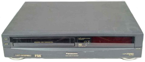
Panasonic
Video cassette Recorder
Type: NV-F55
Operating Instructions

Contents
These operating instructions are split into four sections:
Setting Up
This explains how to set up the VTR for all its uses.
- Connections
- Tuning the TV into your VTR
- Storing TV Broadcasts into your VTR
- Setting the clock of the VTR
- Controls, Indicators and Connection Sockets
- The Video Cassette
Basic Operations
This explains the straight forward operations of playing back a tape and recording.
Additional Functions
This explains other operations you can do such as searching, tape editing and bar code reading.
- Timer Recording
Using the Remote Controller - Search Function
Time Search
Intro Scan - Editing
Copy Editing
Assembly Editing
Insert Editing
Audio Dubbing - Other Functions
The NICAM Broadcast System
Automatic Features
NTSC Playback
NTSC Editing - Bar Code Operation
Scanner Preparation
Setting the Clock
Timer Recording
Helpful Hints
How to use these operating instructions
On-the-spot Recording
The numbers in the illustrations and in the descriptive sentences on each page indicate the sequence of operating steps.
In this way, you can relate a particular control to an action and, where appropriate, to a visual display by the same number.
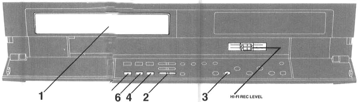
Recording one TV programme while viewing another
1. Use the on-1he-Spot recording operation
2. Select the TV programme on your TV set you wish to view at the present time
Adjustment of the HI-Fl Audio Recording Level
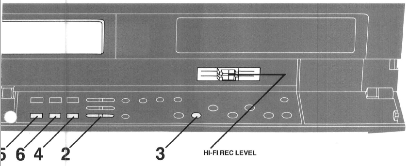
Setting the Hl-FI REC LEVEL to the centre "5" position (click stop) assures satisfaction audio recording results in most cases.
When using the VTR as a Hi-Fi audio recorder of when producing your own video tapes, it may be desirable to adjust the Hi-Fi REC LEVEL to some other position.
(It's recommended to adjust so that peaks in the audio level reach about +4 dB)
• The sound to be recorder on the "normal" audio track wll be adjusted automatically
| Nr. | Operations | Display Symbols | |
| 1 |  |
 |
Insert a cassette tape with an intact erasure prevention tab. • If it has already been inserted , press VTR to turn the unit on |
| 2 |  |
 |
Select the required TV station on the VTA by pressing ∧ ∨. |
| 3 |  |
 |
Select the tape speed SP or LP. |
| 4 |  |
 |
Start recording by pressing REC. • When a Video cassette with broken out tab is inserted, the  indication will flash, and an alarm sound will be duced to indicate that recording is not possible indication will flash, and an alarm sound will be duced to indicate that recording is not possible |
| 5 |  |
 |
To intorrupt recording, press PAUSE/STILL, and press again to continue recording. • II you leave the VTR in the pause mode or more than 5 minutes, the VTR Will automaticaly switch over to the stop mode to protect the tape and the video heads. |
| 6 |  |
To stop recording, press STOP |
Setting Up
Connections
This tells you how to connect with an aerial, TV, etc.
Tuning the TV into your VTR
The VTR supplies signal to the TV set via the RF coaxial cable on channel 36 of the UK broadcasting system. Your TV must be tuned into this channel in order to view the VTR
playback picture. If connection to the TV includes the 21 pin scart cable, the playback picture can be viewed by selecting AV on your TV. The RF coaxial cable must still be connected, but the TV need not be tuned to channel 36.
Storing TV Broadcasts into your VTR
The VTR is fitted with its own TV tuner (just like a normal TV set) and can be tuned to receive up to 99 TV broadcast stations.
Setting the Clock of the VTR
The bui lt-in clock is used to activate the timer for automatic recording and must be set to the correct time.
Setting the Remote Controller
Controls, Indicators and Connection Sockets
This gives a detailed explanation of the function of each button, switch, indicator and connection socket.
Connections
Basic Connections
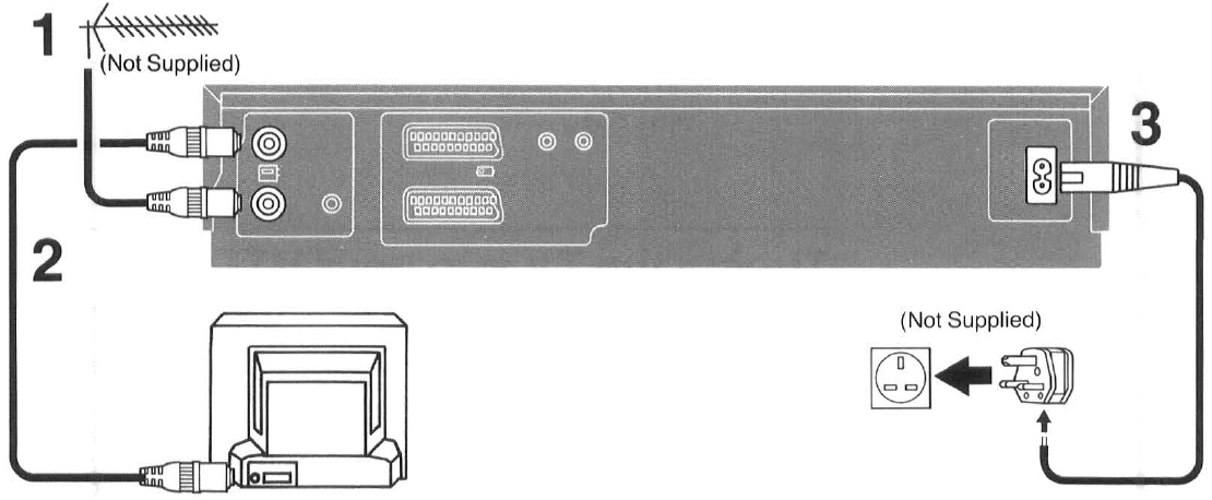
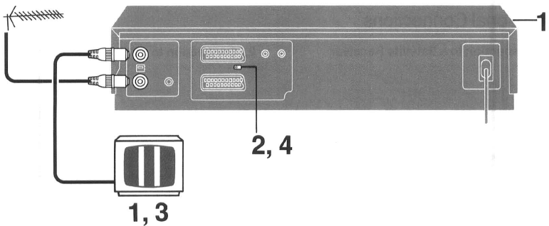
The following connections are required to record and play back the VTR through a TV set:
1 |
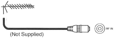 |
Connect an external aerial to RF IN. |
2 |
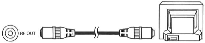 |
Connect RF OUT to the TV aerial connector ( ). ). |
3 |
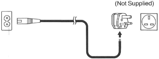 |
Connect the AC mains lead to the AC mains socket. |
Additional Connections
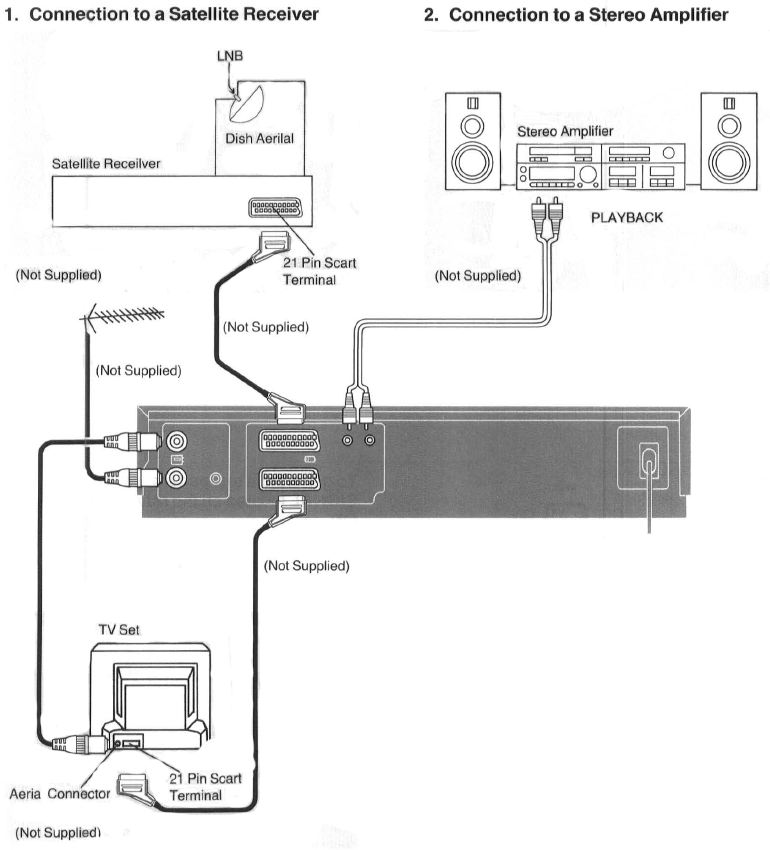
3. Connection to a TV Set with 21 Pin Scart Terminal
The Scart connection is optional but wi ll be required to playback Hi-Fi stereo sound through a stereo TV.
Note:
The satellite signal is only seen when the VTR is on and selected INPUT SELECT AV1.
Tuning the TV into your VT
It is possible to view the video picture on your TV in the same way as you watch TV broadcasts. If you are connecting the video to the TV by the use of
the 21 pin scart terminal then you do not need to follow the procedure mentioned below.
1 |
 |
Turn the TV on. The VTR should also be turned on by pressing VTR on the front panel of the video. |
2 |
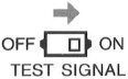 |
To generate a test pattern, set TEST SIGNAL located on the rear of the video to ON. |
3 |
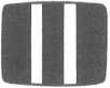 |
Set the TV to a free station number which you wish to use for your video playback i.e. station 5. Follow the tuning procedure for your TV until you can view the TEST BARS. |
4 |
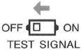 |
After tuning the test bars into the TV, set TEST SIGNAL to OFF. Station 5 is now your video channel. |
|
Note: |
||
| Please note that if the CH ADJ. screw is used then you will have to return your TV to the TEST signal as in item 2 to 4 above. | ||
Storing TV Broadcasts into your VTR
Tuning the TV into your VTR
Storing TV Broadcasts into your VTR
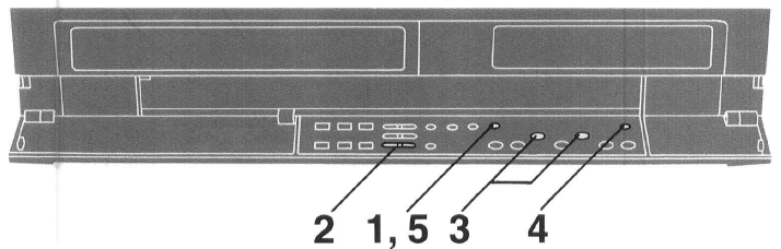
Introduction
The VTR is fitted with its own tuner (just like a normal TV set) and can be pre-set to receive up to 99 TV broadcast stations.
Preparation
Confirm the TV is on and the VTR viewing channel is selected.
| Nr. | Operations | Display Symbols | |
1 |
 |
First, press PRESET/NORMAL. | |
2 |
|
 |
Select station position 1 for tuning using ∧ ∨. |
3 |
 |
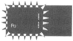 |
To search for the TV station press TRACKING/V-LOCK + or - ; |
4 |
 |
|
To memorize the broadcast station, press MEMORY. •To memorize the other stations repeat steps 2 to 4. |
5 |
|
Once all the broadcast stations are memorized into their appropriate station positions, press PRESET/NORMAL once again to set the VTR to normal operative mode. |
|
| Note: While tuning , your video may lock onto several weak stations from distant transmitters. Should this occur press TRACKING/V-LOCK + or - again until a strong station is received. |
|||
Setting the Clock of the VTR
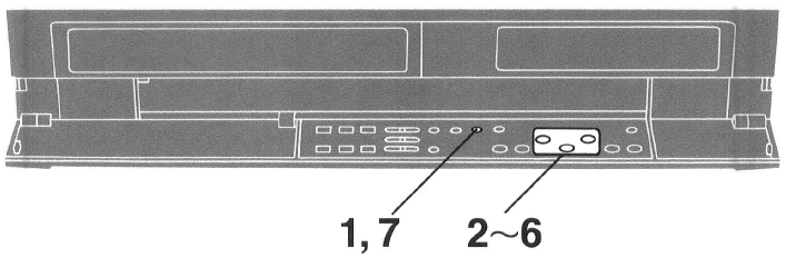
In addition to setting the VTR clock from the remote controller, it can also be set directly from the VTR. The built-in digital clock employs the 24-hour system.
Preparation
Turn ON the VTR.
For Example:
Set the clock for Sunday, October 10, 1999, 20:15.
| Nr. | Operations | Display Symbols | |
1 |
 |
 |
Press CLOCK. |
2 |
|
 |
Set the year by pressing TRACKING/V-LOCK + or - , and then press NEXT. |
3 |
|
 |
Set the month by pressing TRACKING/V-LOCK + or -, and then press NEXT. |
4 |
|
 |
Set the date by pressing TRACKING/V-LOCK + or - , and then press NEXT. |
5 |
|
 |
Set the hour by pressing TRACKING/V-LOCK +or - , and then press NEXT. |
6 |
|
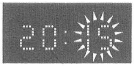 |
Set the minute by pressing TRACKING/V-LOCK +or - . |
7 |
|
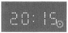 |
To start the clock from this setting, press CLOCK. |
| Note: The clock operates for at least 60 minutes, by its back up system in the event of power failure. |
|||
Controls, Indicators and Connection Sockets
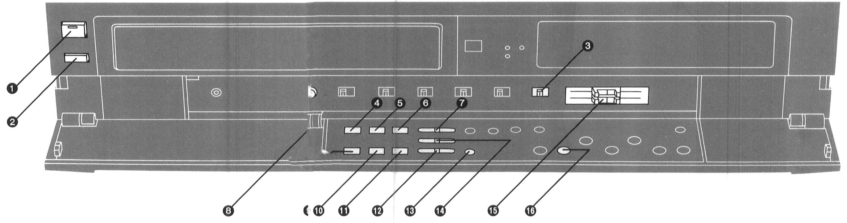
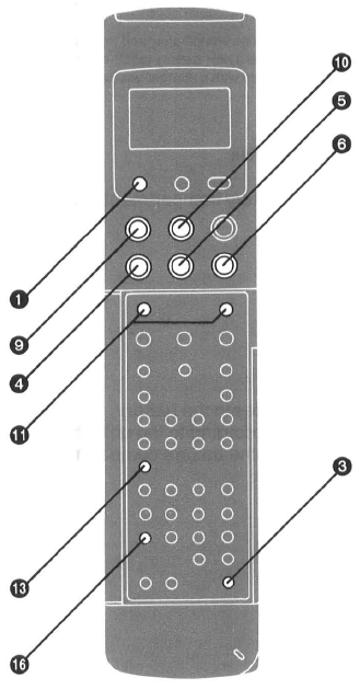 Basic Controls
1 |
VTR (Video Cassette Recorder On/Off) The VTR is turned on and off by pressing this button. The indicator on the button is lit when the VTR is on.
|
2 |
EJECT Press this button to eject the cassette tape. |
3 |
REMOTE MODE (VTR 1/2)
|
4 |
REW (REWIND) Press this button once when the tape is stopped to rapidly rewind it. For short Review playback (during normal playback), keep the button pressed for as long you want the tape to be played back at high speed in reverse direction. For longer Review playback (during normal playback), quickly press the button to start the Review playback. "<<" is lit. |
5 |
PLAY Press this button to start playback. " >" is lit. |
6 |
FF (FAST FORWARD) Press this button once when the tape is stopped to rapidly wind it forward. For short Cue playback (during normal playback), keep the button pressed for as long you want the tape to be played back at high speed in forward direction. For longer Cue playback (during normal playback), quickly press the button to start the Cue playback. ">>" is lit. |
7 |
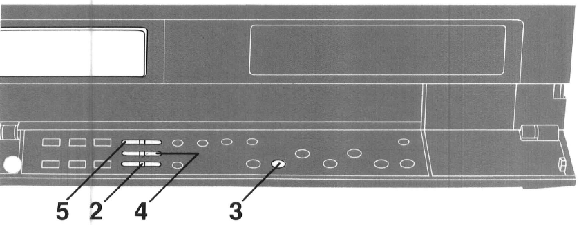
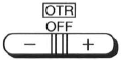
OTA OFF (ONE-TOUCH TIMER RECORDING) Press + or - to set the OTA ending time, "OTA" and "OFF" are lit. A single push changes the time in 1-minute steps, and holding down either button changes the time in 10-minute steps. The OTA OFF buttons must be first pressed within 8 seconds after the OTA starting time has been set, otherwise the starting time will be cancelled. |
8 |
PICTURE Use this control to adjust the sharpness of the picture. It becomes softer when the control is turned to the left, and sharper when turned to the right. |
9 |
PAUSE/STILL Press this button to stop the tape temporarily during playback and recording. Pressing the button again releases the pause. If pressed during playback, a still picture is shown and "OD" is lit.
|
10 |
STOP Press this button to stop any playback or recording. |
11 |
REC Press this button on the VTR to start a recording. The two recording buttons on the remote controller have to be pressed together for the same function. "> REC" is lit. |
12 |
∨∧ Press these buttons to select the required TV station. The VTR can handle up to 99 stations. |
13 |
AUDIO OUT Press this button to select the desired sound tracks. Each press of this button changes the selected sound tracks as follows: Hi-Fi stereo (Land R)- Hi-Fi mono left (L)- Hi-Fi mono right (R)- Normal (Hi-Fi off) ... Hi-Fi Stereo ... |
14 |
OTA ON (ONE-TOUCH TIMER RECORDING) Press + or - to set the OTA starting time. "OTA" and "ON" are lit. A single push changes the time in 1-minute steps, and holding down either button changes the time in 10-minute steps. |
15 |
HI-Fl REC LEVEL Use this control for adjusting the recording level to peak at +4 dB on the recording level indicator. |
16 |
RECORDING SP/LP Press this button to select the tape speed required for recording. SP gives the best picture quality. LP gives the longest recording time. This needs only to be set for recording since the VTR automatically selects the correct speed for playback. |
Additional Controls
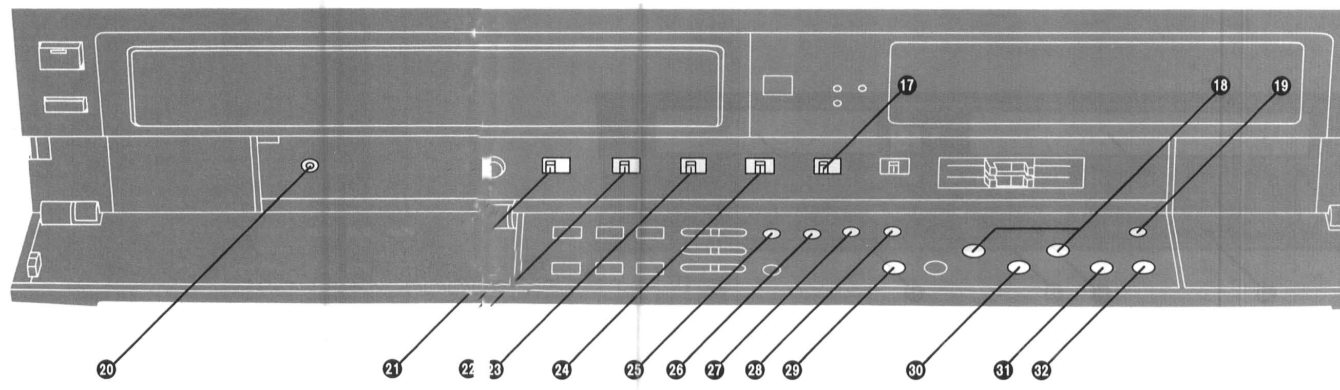
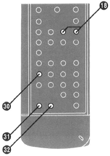
17 |
TAPE SELECT Set this switch according to the cassette tape being used so that the remaining tape time is indicated correctly. - E195: For E30, -60, -80, -120, -180 and -195 tapes. - E240: For E240 tape. - E260: For E260 tape. |
18 |
TRACKING/V-LOCK For manual tracking adjustment The + and - buttons are used to adjust the tracking when, for example, noise bars on the picture are better removed manually than by the automatic digital tracking control. After making a manual adjustment, press both buttons together to return to automatic digital tracking control. Manual tracking adjustment is sometimes necessary to reproduce good Hi-Fi sound and picture quality when playing back tapes that have been recorded on another VTR. For slow tracking adjustment When noise bars appear during Super Still, Super Still Advance or Super Fine Slow playback, switch over to slow playback and adjust with the "+" or " - " Button to reduce the noise bars. For vertical locking adjustment Use the + and - buttons to minimize any vertical jitter during still-picture playback. For setting the clock and timer recording (Remote controller: No function) These buttons are also used for selecting the different lime units when setting the clock to the present time, and for setting the data necessary for timer recording. |
19 |
MEMORY Press this button to memorize the tuner setting for a TV station. |
20 |
MIC Connect a microphone to this socket for recording this socket has priority. |
21 |
HI-Fl/NORMAL MIX Sound is recorded on both the Hi-Fi and normal sound tracks.
|
22 |
NICAM/MONO
|
23 |
NTSC4.43
|
24 |
NOISE FILTER EDIT
|
25 |
AUDIODUB Press this button to set up the VTR for audio dubbing. "A.DUB" is lit. |
26 |
INSERT Press this button to set up the VTR for insert editing. "INSERT" is lit. |
27 |
CLOCK Press this button to initiate date and time settings. After the time has been entered correctly, this button is pressed again to memorize the setting. |
28 |
PRESET/NORMAL Press this button to initiate TV station settings for the tuner. |
29 |
PROG/CHECK This button is used to select the programme number for timer recording. Number " 1, 2, 3 ... or 8" is lit. The button is also used to display details of a preset timer recording. |
30 |
NEXT Press this button to memorize preset data and to change to the next variable when setting the clock or timer. At each push, the flashing indication on the date display changes in the order YEAR, MONTH, DATE, HOUR, MINUTE. |
31 |
TIMERREC This button used to set the VTR for timer recording. When set for timer recording, [El is lit, and the VTR will turn itself on automatically to begin recording at the preset time. The VTR can only be operated manually when the timer recording function is off. Timer recording can be set whether the function is on or off, but recording will only be performed when the function is on. If the timer recording function is on, but no video cassette is inserted or no timer recording has been programmed, the [El will flash to warn that timer recording cannot be performed. |
32 |
CANCEL Press this button to cancel the settings made for a timer recording. |
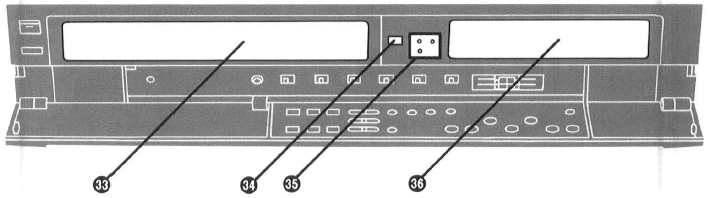
33 |
Cassette Compartment |
34 |
Infra-red Remote Control Receiver Window Receives the signals from the remote controller. |
35 |
Indicator Lamps for M1, M2 and Stereo Reception When receiving a NICAM TV programme, the type of sound system in which it is broadcast is automatically indicated. |
36 |
Multi-Function Display |
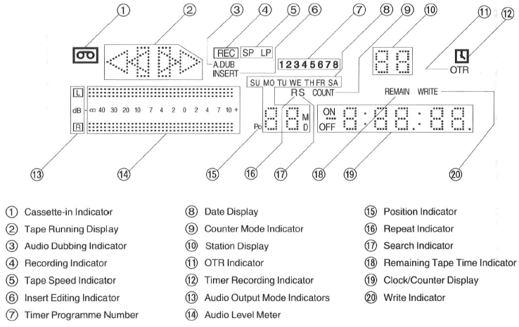
Controls, Indicators and Connection Sockets
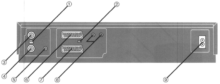
1 |
LEVEL Used to adjust the UHF aerial signal strength. It is normally set to the HIGH position However, if diagonal pattern or stripes appear on picture try setting to LOW position |
2 |
TEST SIGNAL The test signal is transmitted on channel 36. |
3 |
RFOUT Use this to connect to the aerial terminal on a TV set. |
4 |
RFIN Use this to connect an external aerial. |
5 |
CHADJ. Tape playback picture, etc. transmit with channel 36 but if it is occupied by local station, it can be adjusted ± 4ch. |
6
|
AV1/AV2
|
8 |
AUDIOOUT Use these to connect the sound to a stereo audio system. |
9 |
ACIN~ |
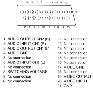
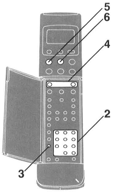
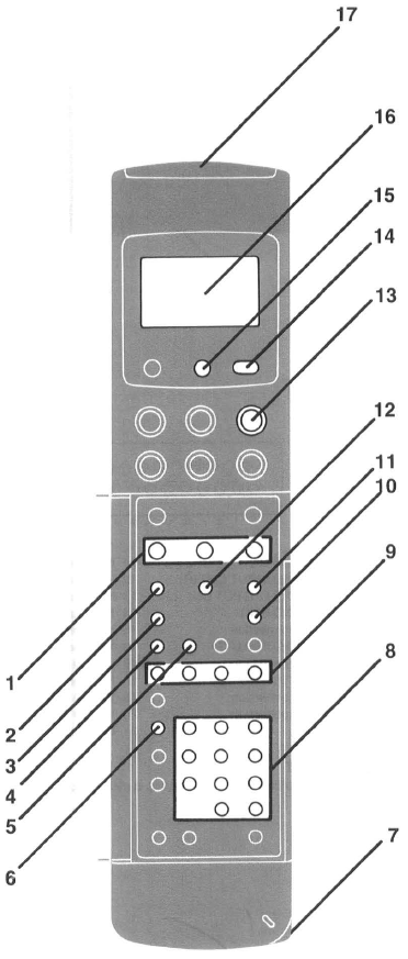 Infra-Red Remote Controller
| 1 | SLOW Press the SLOW Button during playback to switch over to slow motion playback. The slow motion speed can then be adjusted with the (+)or (- ) button. |
9 | AUTOPLAY
|
| 2 | CLOCK/COUNTER This button is used to switch between the display of the clock and the tape counter. The numbers on the tape counter only change for recorded segments of the tape. |
10 | INPUT SELECT Press this button to select the "A 1" or "A2" external recording source.
|
| 3 | MONITOR Keep this button depressed during playback to watch TV broadcast.
|
11 |
RESET
|
| 4 | INDEX For the index search function |
12 | TAPE REMAIN Press this button during playback or recording to have the approximate remaining tape time displayed. "REMAIN" is lit while the remaining tape time is displayed.
|
| 5 | TIME SEARCH For the time search function. |
13 | STILLADV Press this button during still playback. Each time you press this button, the still picture is advanced. |
| 6 | PROG This button used for timer recording by using the remote controller. |
14 | TRANSMIT Press this button to transmit to the VTR data that has been set on the remote controller by either manual means or by bar codes. |
| 7 | Bar Code Reading Section After the Bar Code Reader is turned on, the lip lights in red. |
15 | SCANNER ON/OFF To turn the Bar Code Reader on and off. |
| 8 | Programme Position Selector Buttons
|
16 | Display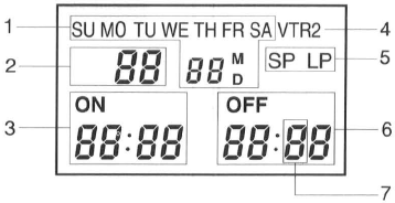 |
| 17 | Infra-red Transmitter The programming data are transmitted from here to the VTR. |
The Video Cassette
| Nr. | Operations | Display Simbols | |
1 |
|
|
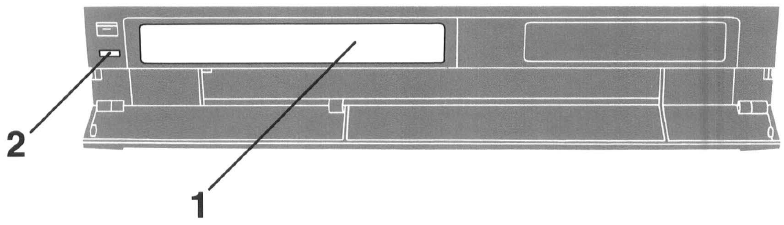
Inserting a Video Cassette (Auto Operation) Insert the video cassette as shown.The VTR will be turned on automatically and the cassette will be automatically drawn into the VTR. |
2 |
 |
Removing a Video Cassette Press EJECT. |
|
 |
Notes:
|
||
Playback
The playback controls allow you to view at normal speed, to search for a specific scene with the tape moving faster than normal, to freeze into a still picture, to advance this still picture frame by frame, and to view in slow-motion.
| Nr. | Operations | Display Simbols | |
1 |
|
|
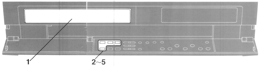
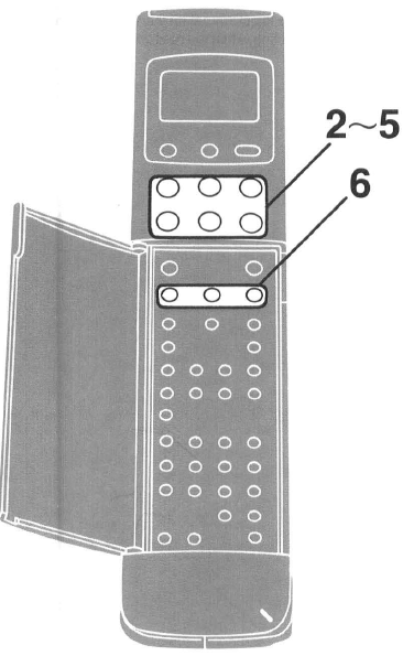
Insert a recorded cassette tape. If it has already been inserted, press VTR to turn the unit on. Turn on the TV and select 21 pin scar! terminal input or station number which has been tuned to channel 36 for VTR playback. |
2 |
 |
 |
Start viewing the picture by pressing PLAY. |
3 |
 |
 |
To search for a specific scene while viewing the picture, press and hold down FF to search ahead. For longer Cue playback, quickly press the button to start the Cue playback. To change back to normal playback, press PLAY. |
4 |
 |
 |
To search for a specific scene while viewing the picture, press and hold down REW to search back. For longer Review playback, quickly press the button to start the Review playback. To change back to normal playback, press PLAY. |
5 |
⇒  |
 |
To interrupt playback for a still picture, press PAUSE/STILL. To continue the normal playback, press PLAY or this button again. To advance one frame of the still picture, press STILL ADV. |
6 |
 |
 |
For a slow-motion picture, press SLOW, and adjust the speed as necessary by pressing + or - . To change back to normal playback, press PLAY. |
Notes:
|
|||
On-the-spot Recording
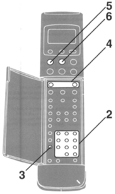
You can record a TV programme without turning on the TV, and you can record one TV programme while viewing another.
| Nr. | Operations | Display Symbols | |
1 |
|
|
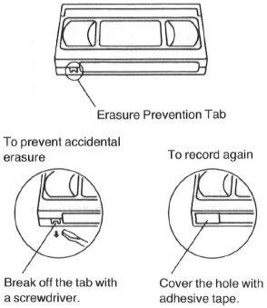
Insert a cassette tape with an intact erasure prevention tab.
|
2 |
|
|
Select the required TV station on the VTR by pressing ∨ ∧. |
3 |
|
|
Select the tape speed SP or LP. |
4 |
|
 |
Start recording by pressing REC.
|
5 |
|
|
To interrupt recording, press PAUSE/STILL, and press again to continue recording.
|
6 |
|
To stop recording, press STOP. | |
|
Recording one TV programme while viewing another Adjustment of the Hi-Fl Audio Recording Level
|
|||
One-Touch Timer Recording (OTR)
OTR allows yot,J to quickly set up the VTR to record a single programme starting within the next 24 hours.
For example: OTR recording of a TV Station 1 from 20:02 to 20:30.
| Nr. | Operations | Display Symbols | |
1 |
|
|
Insert a cassette tape with an intact erasure prevention tab.
|
2 |
|
|
Select the required TV station on the VTR by pressing ∨ ∧. |
3 |
|
|
Select the tape speed SP or LP. |
4 |
 |
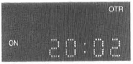 |
Set the starting time by pressing ON.
|
5 |
 |
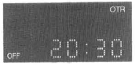 |
Set the ending time by pressing OFF.
|
|
Notes:
To confirm the OTA ending time before the recording starts To confirm the present time during recording |
|||
Additional Functions
Timer Recording
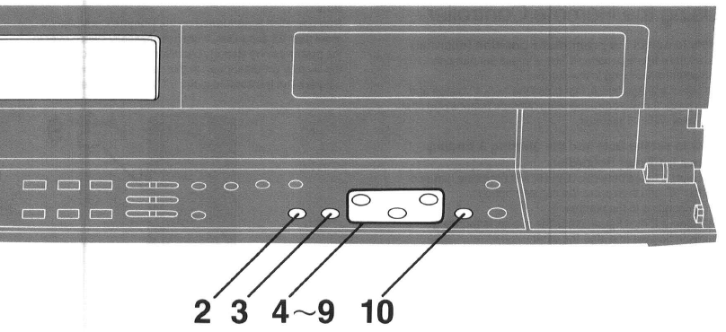
Up to 8 programmes can be recorded up to one month in advance by setting the timer.
This can also handle recording of daily and weekly programmes.
The daily recording can be set according to 3 patterns:
- Monday to Friday
- Monday to Saturday
- Sunday to Saturday
Timer recording can be performed with the Remote Controller (see page 34) and Digital Scanner using the Bar Code Programming Sheet.
For Example:
Programming a timer recording for a TV programme that will be broadcast on Wednesday, October 27, from 20:02 to 21 :30, on programme position (channel) 1, on timer programme number 1. (Present date= October 10, 1999)
| Nr. | Operations | Display Symbols | |
1 |
|
|
Insert a cassette tape with an intact erasure prevention tab.
|
2 |
 |
 |
Select the programme number by pressing PROG/CHECK. |
3 |
|
|
Select the recording speed by pressing RECORDING SP/LP. |
4 |
|
 ⇒ ⇒ |
Select the TV station by pressing TRACKING/V-LOCK + or - and memorize by pressing NEXT. |
5 |
|
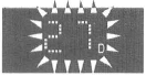 ⇒ ⇒ |
Set the date by pressing TRACKING/VLOCK + or - and memorize by pressing NEXT.
|
6 |
|
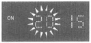 ⇒ ⇒ |
Set the starting time hour by pressing TRACKING/V-LOCK + or - and memorize by pressing NEXT. |
7 |
|
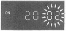 ⇒ ⇒ |
Set the starting time minute by pressing TRACKING/V-LOCK + or - and memorize by pressing NEXT. |
8 |
|
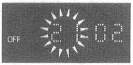 ⇒ ⇒ |
Set the ending time hour by pressing TRACKING/V-LOCK + or - and memorize by pressing NEXT. |
9 |
|
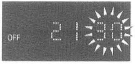 |
Set the ending time minute by pressing TRACKING/V-LOCK + or - .
|
10 |
 |
 |
Activate timer recording by pressing TIMER REC.
|
|
Confirming the timer settings
Note: |
|||
Using the Remote Controller
How to select the programme position (channel)
To select a figure between 1 and 9, press the numeric button corresponding to the number.
To select a 2-digit figure, first press the " -/--" button and then press the two corresponding numeric buttons one after the other within 5 seconds.
How to set the Date and the Starting & Ending Times for Timer Recording
To select a figure between O and 9, first press the numeric button "O" and then press the numeric button corresponding to the number.
To select a 2-digit figure, press the two corresponding numeric buttons one after the other.
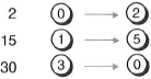
- The second button must be pressed within 5 seconds after the first button.
- Before pressing NEXT, confirm that the figure that you have input is indicated in the proper decimal position in the Display.
- After inputting the minute, confirm that the minutes are indicated as a 2-digit figure, before pressing NEXT.
- If NEXT is pressed while a figure is only indicated in the tens digit, it will be treated as a programming error and will not be accepted.
- However, when no further figure is input within 5 seconds after inputting a single digit, this figure will move to the units digit.
- When pressing the following buttons first, they will immediately be input in the units digit.
For the date: "4"~ "8" Buttons
For the hour: "3"~ "9" Buttons
For the minute: "6"~"9" Buttons
For Example:
When programming a timer recording for a programme that will be broadcast on channel position 4 on the 3rd of the month, from 20:02 to 21 :30.
Note:
If no operation is performed on the Remote Controller for more than 25 secondes, it will automatically switch over to the power-saving standby condition and the indications on the Display will disappear. In this case, the data which have not yet been transmitted to the VTR will be cancelled.
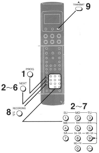
| Nr. | Operations | Display Simbols | |
1 |
 |
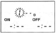 |
Start programming by pressing PROG. The input field for the programme position on the display of the remote control unit flashes. |
2 |
 |
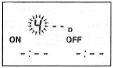 ==> ==> |
Enter the programme position and then press NEXT. |
3 |
|
|
Enter the date and then press NEXT.
Timer Recording on the Same Day Every Week at the Same Time |
4 |
 |
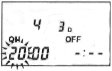 ==> ==> |
Enter the starting time (hour) and then press NEXT. |
5 |
 |
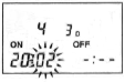 ==> ==> |
Enter the starting time (minute) and then press NEXT. |
6 |
 |
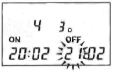 ==> ==> |
Enter the ending time (hour) and then press NEXT. |
7 |
 |
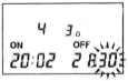 |
Enter the ending time (minutes). |
8 |
|
|
Select the desired tape speed ("SP" or "LP") by pressing RECORDING SP/LP. |
9 |
 |
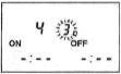
Point the Infra-red Transmitter at the VTR Receiver Window and press TRANSMIT. The transmitted data appear on the display and a repeated beep confirms the reception. |


 ==>
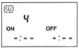
==>
 ==>
==>
| |
Turning Timer On and Off After programming a timer recording, the Timer Recording Indicator  lights up and the VTR can no longer be used for recording and playback. To make it possible to use the VTR, turn off TIMER REC("" goes out). To reactivate the lights up and the VTR can no longer be used for recording and playback. To make it possible to use the VTR, turn off TIMER REC("" goes out). To reactivate thetimer, press this button again. |
|
 |
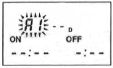 |
Timer Recording from External Picture/Sound Source If Timer Recording is performed by a unit connected to the 21 pin scart terminals, press INPUT SELECT to select the A1 or A2 indicator for the programme position. A1: Through the 21 pin AV1 socket. A2: Through the 21 pin AV2 socket. |
| |
Checking of Timer Programming
Press TRANSMIT.
|
|
 |
Cancelling a Timer Programming To cancel a programmed timer recording, this data must be displayed on the display of the VTR. 1 Press TRANSMIT. •If necessary, press TRANSMIT several times until the desired timer position is displayed. 2 Press CANCEL. •The programmed timer recording will be cancelled and dashes "--" will appear on the display. |
Search Function
VHS Index Search System
It is very easy to find the beginning of each recording, because a special index signal is recorded at the start of each recorded segment on the tape.
Up to 99 index signals can be searched for in both directions.
Time Search
This makes it possible to advance or reverse the tape by a certain period of playback time.
Intro Scan
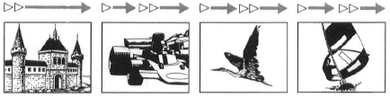
This is used for quickly checking what has been recorded on a tape or for quickly finding a particular recorded segment. A short section of each recorded segment is played back automatically.
Recording of Index Signals
While recording an index signal, the indication "WRITE" lights up for a few seconds. Index signals will be recorded automatically at the start of recording. It is also possible to record an index signal by pressing
REC during record ing. To mark your own reference point.
VHS Index Search System
Preparation
Set the VTR in the normal playback or stop mode.
For example:
Searching for the 2nd recorded segment.
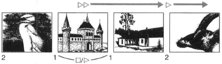
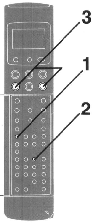
Notes:•The Search function can only count the addressescorrectly, if the index signals are spaced at least3 minutes in the SP mode and 5 minutes in the LP mode.•If these are unrecorded parts on the tape, or if recordingshave repeatedly been made on the same tape portion, theSearch function may not work correctly.​
| Nr. | Operations | Display Symbols | |
1 |
 |
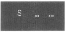 |
Set to index search by pressing INDEX. |
2 |
 |
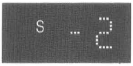 |
Select the 2nd recorded segment by pressing the number 2 button. |
3 |
 |
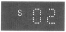 |
Start searching by pressing FF for the forward direction or REW for the reverse direction. •After finding the specific recorded segment, playback starts. |
|
Notes:
|
|||
Time Search
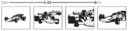
It is easy to search forwards or backwards along the tape by a specific amount of playback time to locate a scene or skip programme items of secondary interest.
Preparation
Insert a recorded cassette tape.
For example:
Searching for the recording 5 min. and 43 sec. after the start of playback.
| Nr. | Operations | Display Symbols | |
1 |
 |
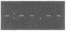 |
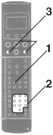
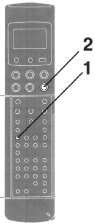
Set to time search by pressing TIME SEARCH. |
2 |
 |
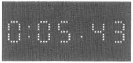 |
Enter the 5 min. and 43 sec. by pressing the number buttons.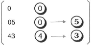 |
3 |
|
Start searching by pressing FF or REW. The playback starts after rewinding or fast forwarding to the tape position of the designated time. |
|
| Note: From stop mode, the searching is activated by fast forward or rewind. From play mode, it is activated by cue or review for less than 1 hour. |
|||
Intro Scan
It is easy to check each recording on tape or to quickly locate a particular recording if its position on tape cannot be remembered.
Preparation
Insert a recorded cassette tape with index signals.
| Nr. | Operations | Display Symbols | |
1 |
|
 |
Set to intro scan by pressing INDEX. |
2 |
 |
 |
Start intro scan by pressing FF.
|
Notes:
|
|||
Editing
Copy Editing
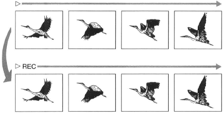
One recorded tape can be copied on to another blank tape.
Assembly Editing
This enables you to record a new segment immediately after a previously recorded segment without any noise between.
Insert Editing
This editing method allows a new recorded segment to be inserted into an existing recording to replace an existing segment of the same length.
Audio Dubbing
This enables you to record new sound on a previously recorded tape.
Copy Editing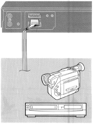
This function is used to make duplicate.
Preparation
Connect a Movie Camera or another VTR to this VTR as shown and select AV1 by pressing INPUT SELECT.
Set NOISE FILTER EDIT to EDIT.
Insert the recorded tape in the already connected video source, and a blank tape into this VTR.
| Nr. | Operaions | Display Symbols | |
1 |
|
|
Play back the recorded tape on the Video source. |
2 |
|
|
Copy the tape by pressing REC on this VTR. |
Note:
|
|||
Assembly Editing
It can be used to make up an Edited tape from several other recordings or video sources. A new scene can be added to the end of a previous one, providing a clean edit without noise.
Preparation
Insert a recorded cassette tape with an intact erasure prevention tab, and select the video source required by pressing INPUT SELECT to set AV1.
Set NOISE FILTER EDIT to EDIT.
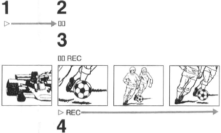
| Nr. | Operations | Display Symbols | |
1 |
|
|
Search for the end of the previously recorded segment by pressing PLAY. |
2 |
|
|
At the end point, press PAUSE/STILL. |
3 |
|
|
Set for the new recording by pressing REC. |
4 |
|
|
Start the new recording by pressing PAUSE/STILL again. |
Insert Editing
It is used to substitute one scene for another providing a noise free Edit to the picture at both the Edit IN and OUT points.
Insert Editing cannot be used on blank sections of tape. In this case use Assemble Editing first.
Preparation
Insert a recorded cassette with an intact erasure prevention tab, and select the video source required by pressing INPUT SELECT to set AV1 .
Set NOISE FILTER EDIT to EDIT.
| Nr. | Operations | Display Symbols | |
1 |
|
|
Search for the end point of the recorded segment you want to replace by pressing PLAY. |
2 |
 |
 |
At the end point, press PAUSE/STILL, and set the counter to 0:00.00 by pressing RESET. |
3 |
|
|
Now search for the starting point of the old recorded segment by pressing REW and holding it down. When you reach the staring point, release REW to stop the tape at this point. |
4 |
 |
 |
Set for editing by pressing INSERT. If you want to replace the sound on the " normal" audio track, too, press AUDIO DUB . (The Audio Dubbing indicator lights up.) |
5 |
|
 |
Start insert editing by pressing PAUSE/STILL again, and the inserted new recording will stop in the still playback mode when the counter reaches 0:00.00. |
Audio Dubbing
It is used to add the back ground music etc.
Preparation
Insert a recorded cassette with an intact erasure prevention tab, and select the audio source required by pressing INPUT SELECT to set AV1 .
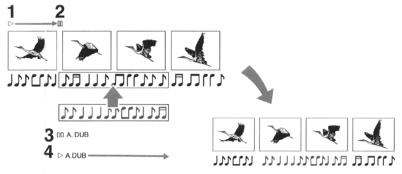
| Nr. | Operations | Display Symbols | |
1 |
|
|
Search for the starting point at which you want to record new sound by pressing PLAY. |
2 |
|
|
At the beginning of the point press PAUSE/STILL. |
3 |
 |
 |
Set for audio dubbing by pressing AUDIO DUB. |
4 |
|
 |
Start recording the new sound by pressing PAUSE/STILL. Stop recording by pressing STOP. |
|
Note: To hear the new sound, select the normal sound track by pressing AUDIO OUT. |
|||
Other Functions
NICAM
The NICAM system is a ground-based TV transmission system for digital stereo sound. This VTR is equipped with a NICAM decoder to receive NICAM broadcasts.
Automatic features
The VTA incorporates a number of automatic features for easy operation.
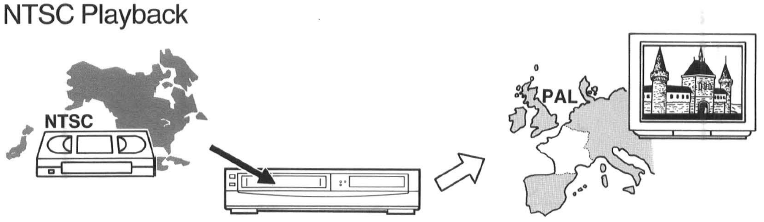
NTSC Playback, Editing
Cassette tapes recorded with the NTSC system can be played back on this VTR through a PAL system TV, al lowing you to enjoy movies direct from the USA, Japan or other countries using the NTSC system.
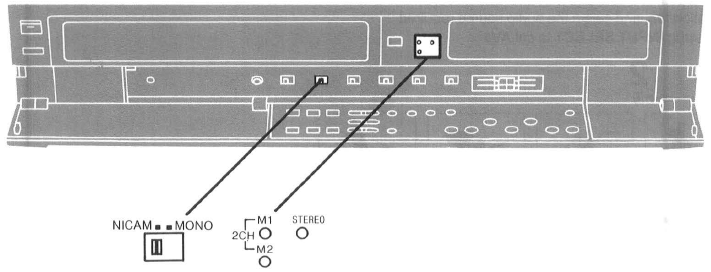
NICAM is a 2 Channel sound broadcast system to provide either a high quality stereo sound track or 2 independant MONO sound tracks, M1 and M2.
NICAM programmes are always accompanied by standard sound broadcasts and you can select the desired sound with NICAM/MONO (when recording) or with AUDIO OUT (when playback) .
The NICAM digital stereo sound can only be recorded on the Hi-Fi audio track.
When a stereo, dual-soundtrack or mono NICAM programme is being received, the indicators are lit to inform you of the type of broadcast.
Reception of a NICAM Stereo Broadcast
When the STEREO indicator is lit, set NICAM/MONO to NICAM to be able to record on the Hi-Fi sound track in stereo. The scart lead must also be connected to a stereo TV in order to hear the NICAM sound in stereo.
Reception of a NICAM Dual-Sound Broadcast
When the M1 and M2 indicators are lit, set NICAM/MONO to NICAM if you want to record both channels on the Hi-Fi sound track. M1 is the left-hand channel and M2 is the right-hand channel.
Reception of a NICAM Monaural Broadcast
When a NICAM monaural broadcast is being received, only the M1 indicator is lit. To hear such a signal on both channels and to record it on both channels of the Hi-Fi track, set NICAM/MONO to NICAM.
- To record the regular sound (ordinary normal sound) on the FM audio tracks when a NICAM programme is received, set NICAM/MONO to MONO.
Important Note tor the NICAM System
When this VTR tuner is switched on, it wi ll automatically switch to a NICAM broadcast, if NICAM is being transmitted. During test transmissions, it is possible that the sound received doesn't correspond to the picture being
viewed . In order to receive a synd,ronized sound and picture, select monaural sound with either AUDIO OUT or with NICAM/MONO. This will only apply until NICAM transmissions are fully operational.
At this time the NICAM signal is transmitted on stereo channels only, since the M1 and M2 formats are not yet available. Even if the soundtrack is in MONO the stereo indicator will remain illuminated.
Note:
Even if the A 1 or A2 programme position is selected, the Audio Recording Mode Indicators may light up according to the type of programme being broadcast on the programme position selected on the VTR. However, this is not a malfunction.
Automatic Features
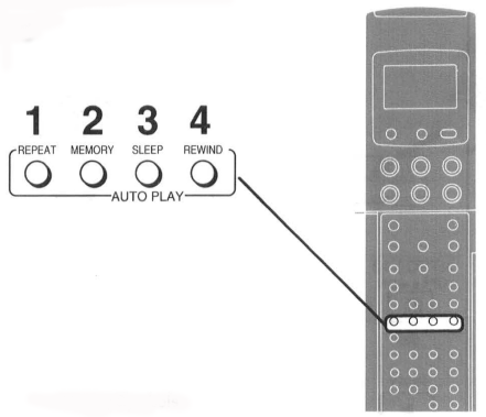
Automatic playback control
| Nr. | Operations | Display Symbols | |
1 |
 |
 |
To repeat playback from the beginning of tape to the end of the recorded segment, press REPEAT. To playback the recording between two index signals, press INDEX and then REPEAT during playback. "RS" is lit. |
2 |
|
To start playback from the counter 0:00.00, press MEMORY. | |
3 |
 |
To play back to the end of the tape, rewind to the beginning of the tape and then turns itself off automatically, press SLEEP. | |
4 |
 |
To rewind the tape to the beginning and then start playback, press REWIND. | |
|
Automatic switching on Automatic playback Automatic rewinding Automatic switching off and ejection Automatic head cleaning |
|||
| Nr. | Operations | |
1 |
 |
Set NTSC 4.43 to OFF. |
2 |
|
Insert the NTSC cassette tape and play back by pressing PLAY. |
|
Note: This system is a modified version of the NTSC broadcasting system to allow most UK TV's to reproduce a colour picture when an NTSC tape is replayed on this VTR. However due to the system change, the picture may shrink, roll or not reproduce colour on some Televisions. During playback of NTSC recordings, the Tape Counter does not function correctly. |
||
NTSC Editing
Connect 2 VTRs which has NTSC 4.43 Switch.
Ensure NOISE FILTER EDIT is set to EDIT.
| Nr. | Operations | |
1 |
 |
Set NTSC 4.43 to ON for both VTRs. |
2 |
Start recording same as page 40- 43. | |
3 |
|
Set back the NTSC 4.43 to OFF. |
Bar Code Operation
A bar code digital scanner is built into the remote controller so that you can set the programme recording timer simply by reading appropriate bar codes.
Scanner Preparation
Operating the Remote Controller
This remote contro ller also operates as a digital-scanning bar code reader.
Press SCANNER ON/OFF to turn it on.
If the remote controller is not operated within 25 seconds (within 4 minutes when setting the clock time), it will automatically switch over to the power-saving standby condition and the lamp will go off. (In this conqition, if bar
codes have already been read but not yet transmitted to the VTR, the data will be cancelled.)
When the lamp is not lit, press SCANNER ON/OFF to turn it on again.
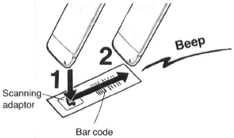
Reading the bar codes
- Fit the remote controller to the scanning adaptor.
- Trace the bar code quickly in the direction of the arrow, ensuring that you trace it completely past the last bar. The "Beep" sound indicates that the bar code has been read completely.
When the Bar Codes Cannot be Read
Although the lamp in the tip of the Bar Code Reading Section lights up:
- No figures appear in the Display
- No beep sounds is heard; The tip of the Bar Code Reading Section is probably clogged with dirt.
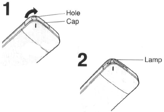
Cleaning
- Remove the cap of the Bar Code Reading Section.
•Remove dirt and dust from the hole of the cap. - Gently wipe the tip of the lamp with a soft cloth.
•Reattach the cap by inserting it until it locks with a click.
Remote Control Modes
Adjust the remote control mode of the Digital Scanner to the same remote control mode (VTR 1 or VTR 2) as selected on the VTR itself.
When Remote Control Mode "VTR 2" is selected on the VTR
Trace the "VTR 2" bar code on the Programming Sheet.
- "VTR 2" wi ll appear in the Bar Code Reader Display. When the "VTR 1" bar code is traced, the "VTR 2" indication will disappear and the remote control mode is changed back to "VTR 1".
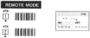
Note: There is no indication-on the display for "VTR 1 ".
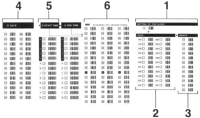
Setting the Clock
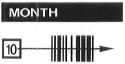
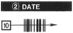
Read in the following data successively by tracing bar codes 1 to 6 on the programming sheet.
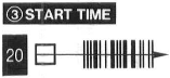
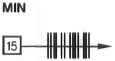
For Example: Set the clock for Sunday, October 10, 1999, 20:15.
Preparation
Turn on the VTR and the remote controller.
| Nr. | Operations | Display Symbols | |
1 |
 |
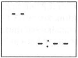 |
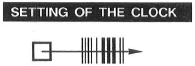
Trace the bar code SETTING OF THE CLOCK. |
2 |
 |
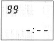 |
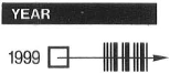
Trace the bar code for the year (YEAR). |
3 |
 |
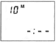 |
Trace the bar code for the month (MONTH). |
4 |
 |
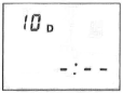 |
Trace the bar code for the day of the month (DATE). |
5 |
 |
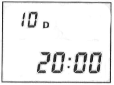 |
Trace the bar code for the hour (START TIME).
|
6 |
 |
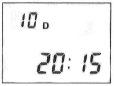 |
Trace the bar code for the minute (MIN).
|
7 |
|
To transmit the data to the VTR, point the remote controller at the reception window on the VTR and press TRANSMIT.
|
|
8 |
 |
To turn off the remote controller, press ON/OFF again.
|
Timer Recording
Setting Timer Recordings from Bar Codes
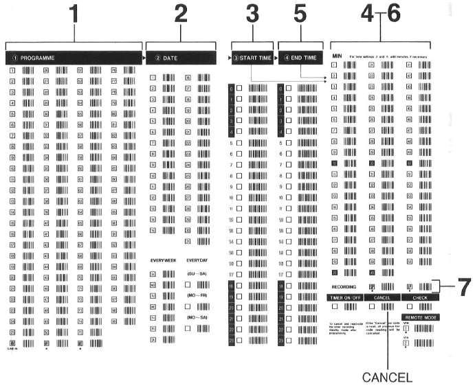
Successively scan the data for the programme channel, day, starting time and ending time by tracing bar codes 1 to 7 on the programming chart.
Preparation
Turn on the VTR and the remote controller.
For Example:
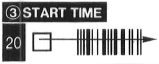
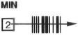
When programming a timer recording for a programme that will be broadcast on programme position 4 on the 3rd of the month, from 20:02 to 21 :30.
| Nr. | Operations | Display Symbols | |
1 |
 |
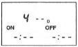 |
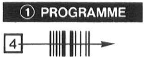
Trace the bar code for PROGRAMME. |
2 |
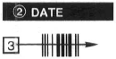 |
Trace the bar code for DATE. | |
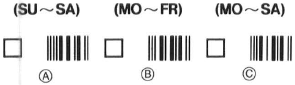 |
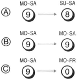
Timer Recording Every Day at the Same Time For this timer setting, three day patterns can be selected: ® Daily recording from Sunday to Saturday @ Daily recording from Monday to Friday © Daily recording from Monday to Saturday |
||
 |
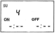 |
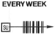
Timer Recording at the Same Time on the Same Day Every Week Trace the bar code for the day of the week in the EVERYWEEK column. For example, SU (Sunday). |
|
3 |
 |
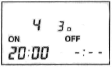 |
Trace the bar code for START TIME. |
4 |
 |
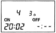 |
Trace the bar code for MIN. |
5 |
 |
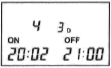 |
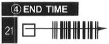
Trace the bar code for END TIME.
|
6 |
 |
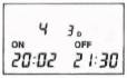 |
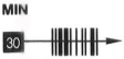
Trace the bar code for MIN.
|
7 |
 |
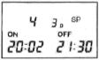 |
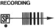
Trace the bar code for RECORDING according to the desired tape speed.
|
8 |
|
To transmit the data to the VTR, point at the reception window on the VTR and press TRANSMIT.
Programming a Series Timer Recordings |
|
9 |
|
To turn off the remote controller press SCANNER ON/OFF. | |
 |
 |
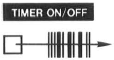
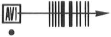
Turning the Timer on and off After programming a timer recording, the timer recording indicator" " lights up, and the VTR can no longer be used for normal recording and playback. To make it possible to use the VTR, trace the TIMER ON/OFF bar code and transmit to the VTR (the timer recording indicator "" will go out). To reactivate the timer again, trace the TIMER ON/OFF bar code again and transmit to the VTR (the "" indicator will light again). |
 |
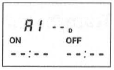 |
Timer Recording from an External Signal Source If a timer recording is to be made from a signal source that is connected to the 21 pin scart terminal, the "AV" bar code in the CHANNEL column must be traced for the programme. AV 1: AV1 socket AV 2: AV2 socket |
 |
|
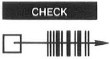
Checking Timer Recording Settings
|
 |
 |
Cancelling Timer Recording Data
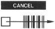
The programmed timer recording will be cancelled and " - " dashes will appear on the display panel. |
Before Requesting Service
Before requesting service, check the following points once again.
VTR will not operate correctly |
|||
SYMPTOM |
CAUSE |
REMEDY |
CHECKED |
| Multi-function display is not illuminated. | Mains lead not connected. | Reconnect mains lead to VTR and ensure switched on at mains plug. | |
| Fuse blown in plug. | Fuse cannot easily be checked . Replace fuse with known good one and check plug wiring. | ||
| Multi-function display is illuminated but VTR will not operatewhen VTR pressed.​ | VTR in timer mode. | Press TIMER REC to operate VTR manually. | |
| Safety devices operating. | Disconnect mains lead and wait for 1 minute. Reconnect mains supply and check functions. |
||
| VTR will operate for a few seconds then power off. | Tape jammed in VTR . | If tape jammed in VTR do not attempt to remove, as this may cause damage. Consult your dealer for advice. | |
Playback functions defective |
|||
| SYMPTOM | CAUSE | REMEDY | CHECKED |
| Picture noisy or not in colour. | Not tracking correctly. | Although auto-tracking should ensure a good picture it may be necessary to manually adjust tracking on some tapes not recorded on this VTR. | |
| TV set not tuned to VTR. | Operate test switch on VTR and check TV tuning . | ||
| Tape recorded incorrectly. | Check aerial connected to VTR. | ||
| Check each programme station in tune. A snowy picture on one or more programmes may indicate VTR tuned to weak station or wrong transmitter. Re-tune if necessary. |
|||
| If timer record was used, confirm that a programme number had been selected that was correctly tuned. | |||
| Video heads clogged. | Condensation may have formed, or a faulty tape has been used. See Tape Care and Video Head Clogging. Do not operate VTR for 1 hour then insert a new tape (the original may be faulty) and playback for a few minutes. If fault does not clear consult your dealer for further advise. | ||
| Video head worn. | Carry out same procedure as for clogged video heads. If fault does not clear consult your dealer for advice. | ||
| Good black & white picture but no colour. | NTSC 4.43 incorrectly set. | Set NTSC 4.43 to OFF. To play back both PAL and NTSC tapes on your TV. | |
| Horizontal bars or lines run down picture or appear stationary. | Tape defective due to surface damage or wear. | Confirm other tape OK and replace defective tape. See separate section on tape care. | |
| Video heads may be worn or service requir. | Consult your dealer for further advice. | ||
| VTR goes into auto rewind mode while playing tape. | Tape defective due to surface damage or wear causing end of tape detection to operate. | Replace defective tape. | |
Record functions defective​ |
|||
| SYMPTOM | CAUSE | REMEDY | CHECKED |
| Alarm sound is produced and "" indication flashes when ever recording is attempted. |
Erasure prevention tab on cassette is broken out. | Use tape with intact erasure prevention tab or cover tab hole with adhesive tape, if original recording is no longer required. | |
| Picture is recorded with noise or blank screen.​ | Aerial or aerial lead defective. | Check aerial connection to VTR. Check your normal TV picture. If no picture check your aerial. | |
| VTR is not correctly tuned. | Re-tune VTR. Ensure input selector set to TV programme. | ||
| Input selector is not correctly set. | Press INPUT SELECT to select AV1 , AV2, for external source or select TV programme. | ||
| OTR will not function. | Clock is flashing 0:00. | Set clock to present time. (Note this is a 24 hour clock) | |
| Timer recording cannot be periormed. (With controls on VTR)​ | Clock or calendar incorrectly set. | Check clock and calendar. Set to present time. (Note this is a 24 hour clock). | |
| Clock is flashing 0:00. | Set clock to present time. | ||
| Recording start or stop time setting incorrect. | Set recording start and stop time correctly. Try a short timer recording a few minutes ahead of the present time to confirm correct operation. | ||
| VTR not set for timer recording. | After setting up timer recording set timer rec to on. | ||
| AV1 , AV2 external recordings cannot be made.​ | Input Selector is not correctly set. | Select AV1 , AV2. | |
| External AV connections incorrect. | Check connections for external video and audio source are correct. | ||
Remote control functions defective |
|||
| SYMPTOM | CAUSE | REMEDY | CHECKED |
| Remote controller does not operate correctly. | Remote controller transmitter beam not reaching VTR. | Ensure remote controller is being pointed at VTR and that transmitter beam is not obstructed. | |
| Distance is too far. | Use remote controller within 7 m of VTR. If range is reduced, replace batteries. | ||
| Batteries are exhausted. | Replace batteries by type UM3 or R6 type availabel from your dealer | ||
| Batteries incorrectly fitted ( + - ) Reversed. | Fit batteries correctly | ||
| Remote control! mode of the VTR and the Remote Controller do not match. | Set the same remote controll mode. Either VTR 1 or VTR 2. | ||
| Bar code read ing not possible. | Remote controller in power saving condition. | Press SCANNER ON/OFF to turn it on again. | |
| Bar code not traced correctly. | Practice tracing the bar code from left to right. Each bar code should take around half a second to trace. A beep indicates bar code is read correctly. | ||
| Bar code sensor cap blocked. | Remove sensor cap and clean. | ||
| Bar code data cannot be transmitted to VTR. | VTR is turned off or is in timer mode. | Turn VTR on. | |
| VTR is operating. | Stop VTR. | ||
| Timer record memory is full. | Cancel timer recording to enter a new timer event or wait until one timer event has taken place. | ||
| Bar code reading was not followed by a repeated bleep. | Read bar code again. | ||
| Remote control I mode of the VTR and the Remote Controller do not match. | Set the same remote control! mode. Either VTR 1 or VTR 2. | ||
Precautions
Please read these cautions before you operate this VTR .
Cassette Compartment Door
When first unpacking the unit, you may notice that the cassette compartment door is partially open. This condition is due to the operation of a safety device designed to protect the unit from vibration during shipment; it is not a malfunction. When the AC mains lead is connected to a
mains outlet, the door will return to its original position.
Avoid Sudden Changes in Temperature
If the VTR is suddenly moved from a cold place to a warm place, moisture may form on the tape and inside the VTR.
Humidity and Dust
Avoid places where there is high humidity or much dust, which may cause damage to internal parts.
Do Not Obstruct the Ventilation Holes
The Ventilation holes prevent abnormal increase in temperature. Do not block or cover these holes. Especially avoid covering the holes with soft materials such as cloth or paper
Keep away from High Temperature
Keep the VTR away from extreme direct heat such as direct sunlight, heating rad iators, or closed automobiles.
Keep Magnets away
Never bring a magnet or magnetized object near the VTR because it will adversely affect the performance of the VTR.
No Fingers or Other Objects Inside
Touching internal parts of this VTR is dangerous, and may cause serious damage to the VTR . Do not attempt to disassemble the VTR. There are no user serviceable parts inside.
Keep Water away
Keep the VTR away form flower vases, tubs, sinks, etc. CAUTION: If liquids are spilled into the VTR, serious damage could occur. If you spill any liquid into the VTR, consult qualified service personnel.
Lightning
To avoid damage by lightning, disconnect the aerial plug from the VTR.
Cleaning the VTR
Wipe the VTR with a clean, dry cloth . Never use cleaning fluid, or other chemicals. And do not use compressed air to remove dust.
Stacking
Place the VTR in a horizontal position, and do not place anything heavy on it.
Video Head Clogging
The video heads place picture signals on the tape during recording and read picture signals from the tape during playback and they are, therefore, of critical importance for the picture quality. To ensure that they can always provide optimum picture quality, this VTR is equipped with an Auto Head Cleaning Function that removes tape particles and dust from the video heads. However, if the VTR is used over extremely long periods of time, these heads may stil l become dirty and clogged. In such a case, the signals can no longer be recorded correctly, and the playback picture will be distorted accordingly. This is the case, for example, during the playback of a tape, the sound is reproduced normally, but no picture is seen, or the picture is greatly distorted. When such a symptom occurs consult your
dealer for further advice.
Condensation may form in the VTR if:
- The VTR is in a room where the heater has just been turned on.
- The VTR is in a room with steam or high humidity.
- The VTR is brought from cold surroundings into a well-heated room.
- The VTR is suddenly brought from cool surroundings, such as an air-conditioned room or car, to a place which is hot and humid.
Note:
Do not operate the VTR for at least 1 hour if any of the above conditions occur. This VTR does not incorporate a dew sensor.
Tape Care
Some do's and don'ts on tape care.
DO:
- Use a good quality branded tape , such as Panasonic.
- Keep in the Box supplied with your tape, or a video case, when not in use.
- Try to use all the tape on a cassette by making recordings not only at the tape start but also in the middle and end sections. This will avoid many repeated recordings at the beginning of the tape resulting in premature wear.
- Take care to insert a tape correctly in to the VTR to avoid damage.
DO NOT:
- Expose the tape to high humidity or temperature.
- Expose to liquid.
- Expose to dust particles by storing directly on a carpet for example.
- Use a damaged tape or attempt to repair.
- Dismantle the cassette housing.
- Attempt to lift the front cassette flap or touch the tape surface.
Specifications
NV-F55B ... (U.K. model)
Information for Your Safety
Power Source: 220-240 V AC 50-60 Hz
Power Consumption: Approx. 29 watts
| Video Recording System: | 2 rotary heads, helical scanning system |
| Video Heads: | 4 heads |
| Tape Speed: | SP; 23.39 mm/sec. LP; 11.7 mm/sec. |
| Tape Format: | VHS tape |
| Record/Playback Time: | SP; 240 min. with NV-E240 LP; 480 min. with NV-E240 |
| FF/REW Time: | Approx. 2.5 min with NV-E180 |
VIDEO
| Television System: |
CCIR; 625 lines, 50 fields, PAL colour signal |
| Modulation System: | Luminance; FM azimuth recording Colour signal; converted subcarrier phase shift recording |
| Input Level: | AV; 1.0 Vp-p, 75ohm |
| Output Level: |
AV; 1.0 Vp-p, 75ohm |
AUDIO
| Input Level: | AV; more than - 6 dBV, more than 10 kohm MICROPHONE; - 70 dBV, |
| Output Level: | AV; - 6d8~ less than 1 kohm AUDIO OUT (PHONO); - 8 dBV, less than 1 kohm |
| Audio Track: | 1 track (Normal-mono only), 2 channels {Hi-Fi sound-stereo) |
| Video Horizontal Resolution: | Colour; more than 240 lines (SP) |
| Signal-to-Noise Ratio: | Video; more than 43 dB (SP) |
| Dynamic Range: | Audio; more than 90 dB (Hi-Fi audio track) |
| Audio Frequency Response: | 20 Hz-20 kHz (Hi-Fi audio track) |
| Wow and Flutter: | 0.005 % Wrms/Hi-Fi |
| Operating Temperature: | 5°C- 40°C |
| Operating Humidity: | 35 %-80 % |
| Weight: | 5,4 kg |
| Dimensions: | 430 (W) x 96 (H) x 356 (D) mm |
| Standard Accessories: | 1 pc. Remote Controller 2 pcs. "R6" size batteries 1 pc. Bar code sheet 1 pc. AC Mains Lead 1 pc. DIN-DIN Coaxial Cable 1 pc. Audio Cable |
Weight and dimensions shown are approximate.
Specifications are subject to change without notice.
Quick Reference
Turn the VTR on
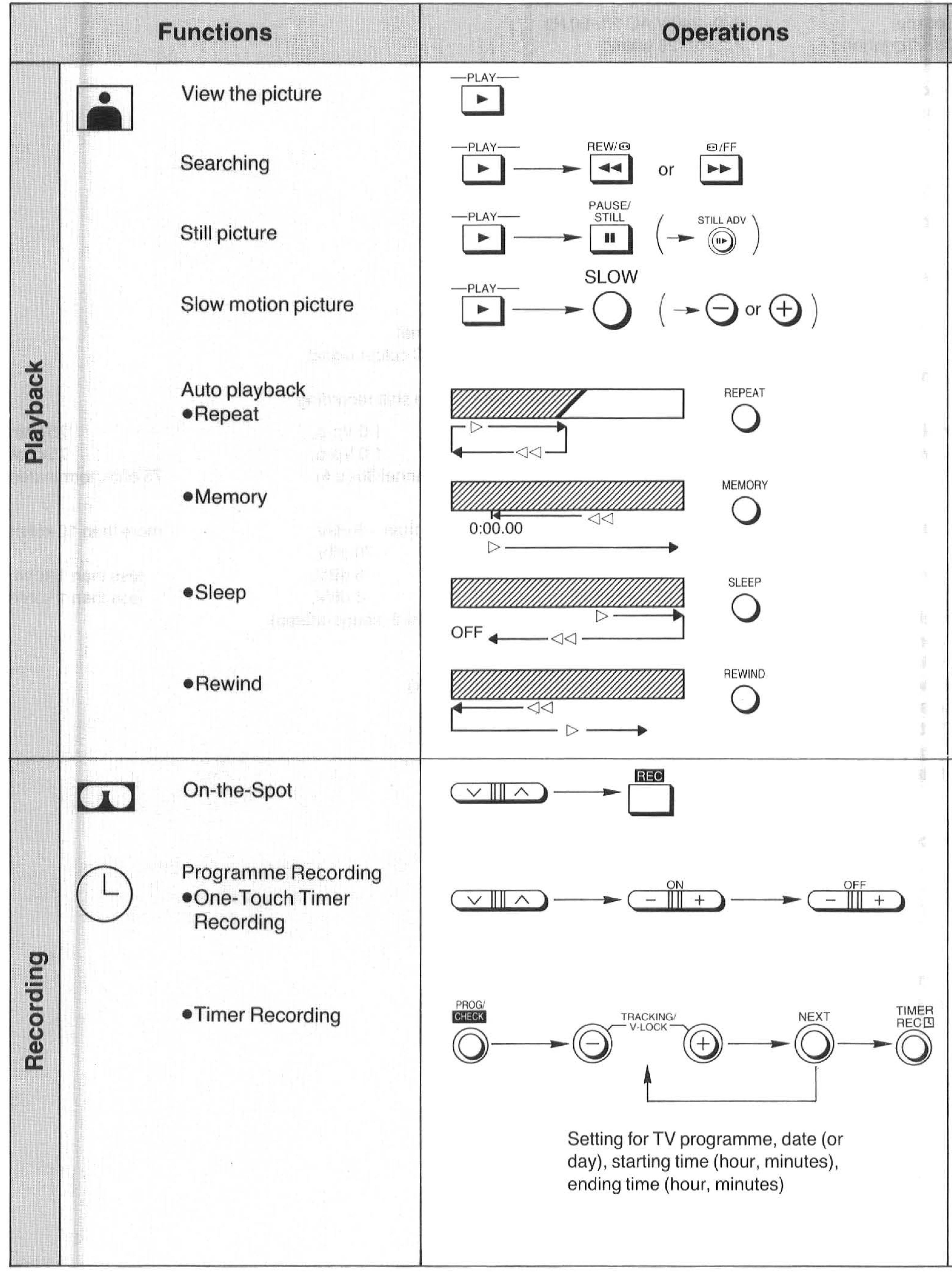
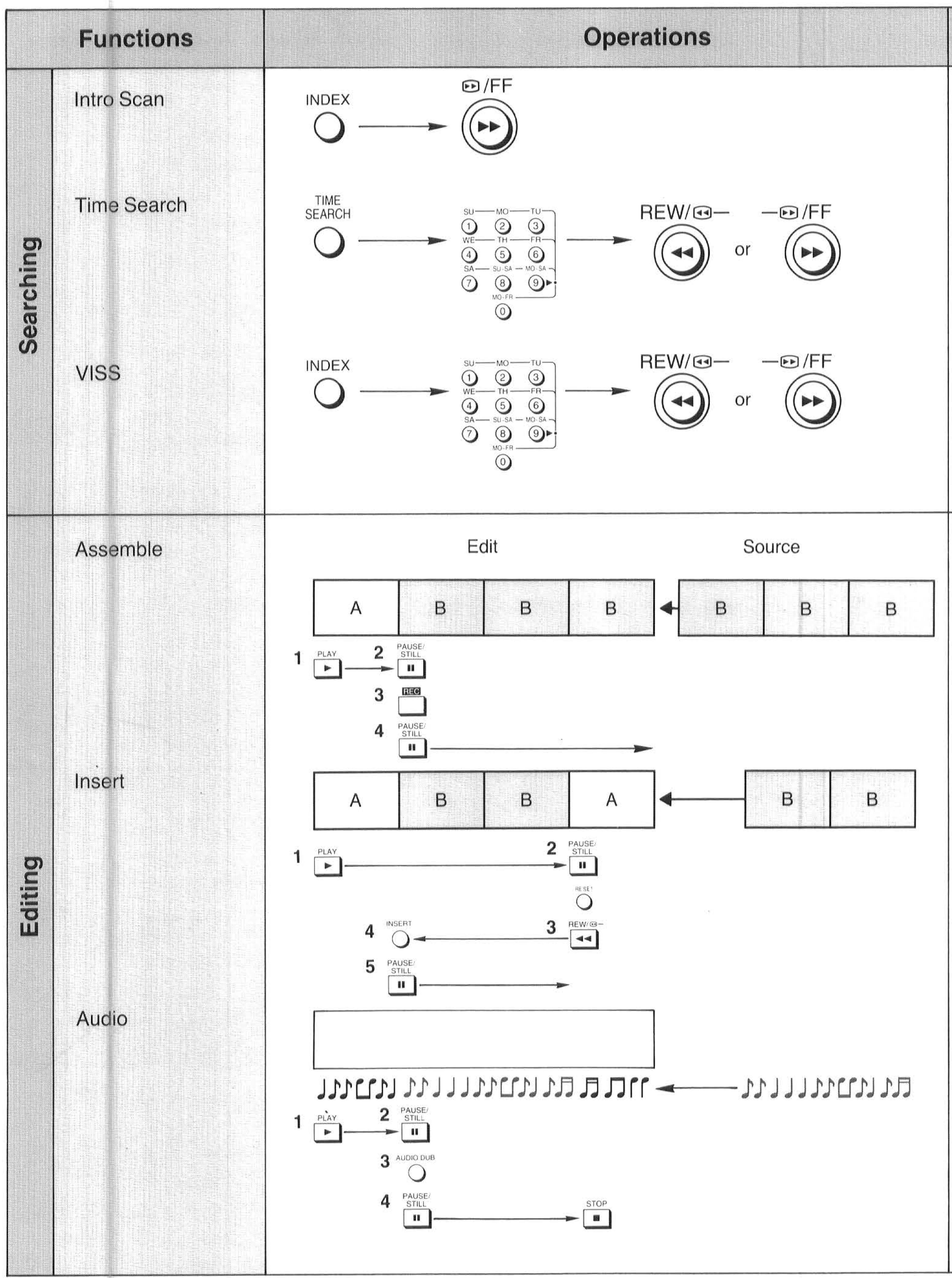
Insert Cassette tape